Intelligent 3D LED Smart Alarm Clock
This the final project for course ECE 5725 Embedded Operating System at Cornell University (2023 Fall). Me and my team members build an intelligent 3D LED smart alarm clock with LED panels bought from Adafruit, 3D printed frameworks and specially designed software based on open source libraries.
Introduction
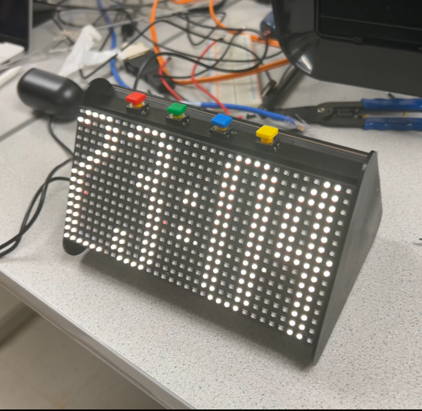
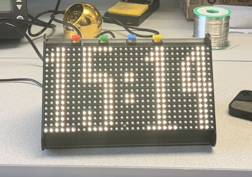
Intelligent 3D LED Smart Alarm Clock is an compact designed electronic object that integrates functions like displaying current time, set alarm and make an alarm sound when the set time is reached, switch to different special displaying effects when accelerometer detects pose change, etc.
It comprises three LED panels, each has 16x32 pixels, all three panels are installed in the 3D printed base with magnets so they are all dismountable. Three panels form a triangular space, where Raspberry Pi 4B, LED matrix driver hat, accelerometer and button related circuitry are installed inside of it.
The RGB matrix driver hat produced by Adafruit is used to drive the LED panels. We employed the open source library rpi-rgb-led-matrix and created many interfaces on top of it to better control all the displaying details in pixel accuracy.
This is a team work conducted by:
- Ding Yang dy297@cornell.edu
- Steve Wang sw2327@cornell.edu
- Keyun Gao kg535@cornell.edu
The code of this project is on GitHub: steve-z-wang/ece5725-final-project (github.com)
Product Functions
Default mode
The default mode, when the clock is held horizontally, the time will automatically show on the side that aims directly at users; when the clock is held vertically, the digits of time will fall down to the ground side like sand; when the clock is held horizontally again, the “sand of time” will backtrack to their starting position to form the original time.
Alarm setting mode
This mode allows users to set the alarm time by two buttons, one for selecting hour or minute, and the other for incrementing the set time.
Zen mode
All three panels display the selected picture in a scrolling way (by default Tai Chi diagram)
Snowflake mode
Simulate 100 pixels in one panel like snowflakes, they will fall and bounce between the sides with the change of pose, which is achieved by reading data from the accelerometer inside the clock.
Framework Design
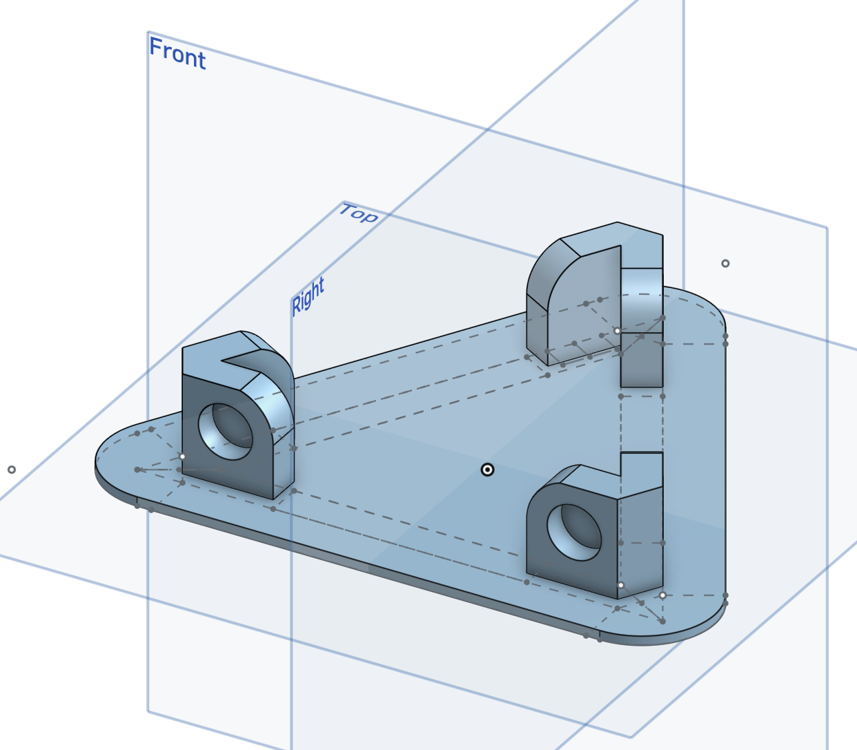
All the 3D printed objects are designed in [Onshape](Onshape | Product Development Platform), an online CAD software system that helps create different 3D models and assemblies.
The 3D printed case for our project is composed of 2 bases and 3 side bars.
Base
Side Bars
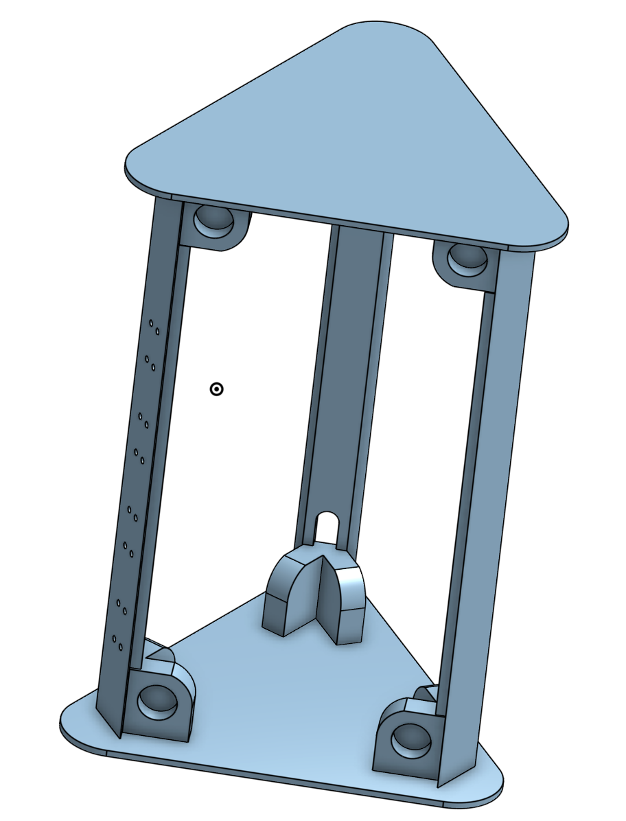
The overall structure of three side panels are the same, but they differ in a few details.
- One has 16 holes designed to install 4 buttons.
- One has a long notch on one side to let power cable and speaker cable go through.
- The shape of them is designed to better fit between the bases and the panels without the help of screws or glue.
Assembly
Two bases and three side bars are put together with the help of magnets.
We avoid using glues, so that each part can be easily disassembled and replaced.
Magnets and Screws

Hardware Design
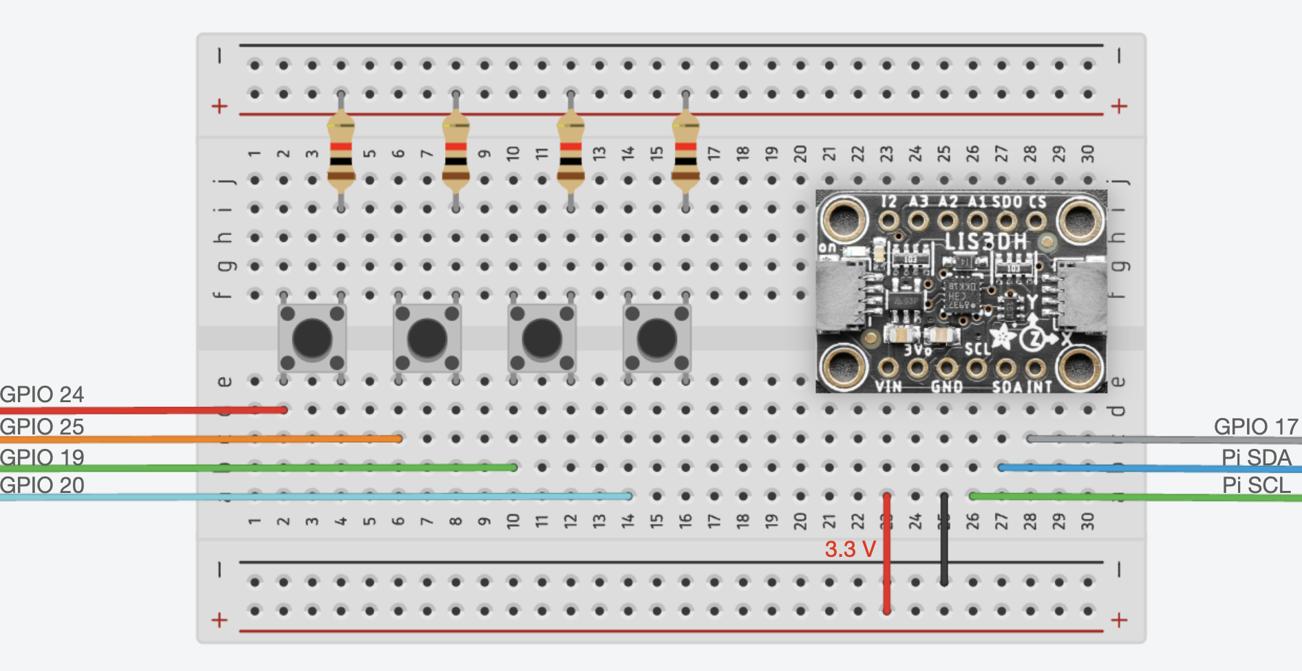
The hardware design is shown below, we have four buttons and one accelerometor in the circuit.
They need seven GPIO pins to connect to the RPi.
The buttons are pulled down in our code, so no pull down circuit in our circuit.
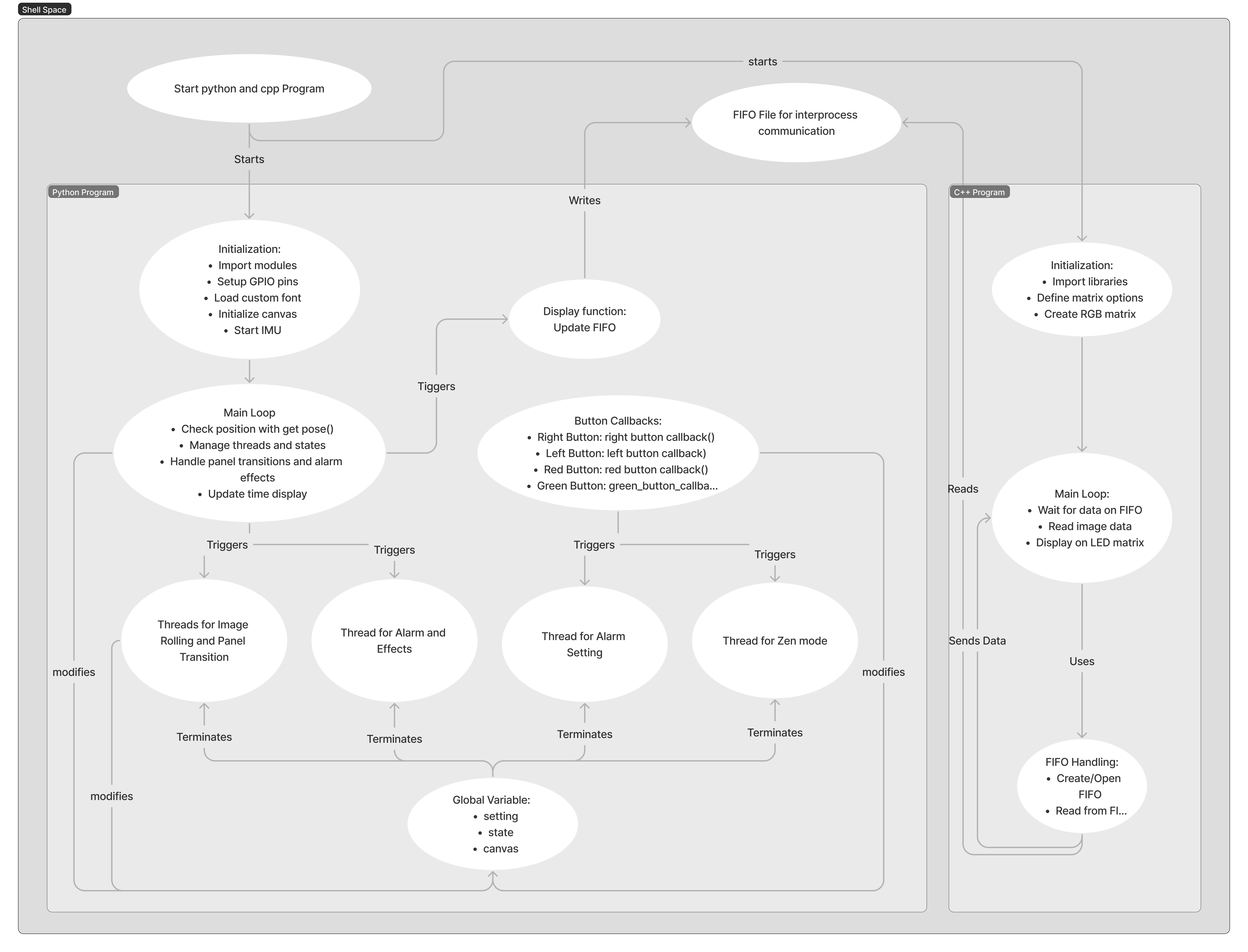
Software Design
This is an outline for our software design.
It contains cpp programs, python programs and shell scripts.
It also utilized FIFO to communicate between different processes.
Demonstration
Default Mode
Horizontal Scroll
Vertical Falling
Horizontal Recovering
Alarm Setting Mode
Set Hours
Set Minutes
Zen Mode
Snowflake Mode
References
Intelligent 3D LED Smart Alarm Clock
https://yang-d19.github.io/Intelligent-3D-LED-Smart-Alarm-Clock/