Lab6
Prelab
1. Clearly describe how you handle sending and receiving data over Bluetooth
In my code, I record the state of the robot in every loop, including timestamp in millisecond, yaw angle, setpoint of yaw angle and the controller value of both side drivers.
During the auto running process where the robot tries to maintain the given status, the transmission over bluetooth is forbiddened to ensure the high frequency of controll loop.
When the controlling process is over, user can send the command “GET_HISTORY_DATA” over bluetooth which will notify the robot to send all of its history records to the laptop over bluetooth. The jupyter server running on the laptop will use a callback function to deal with the history records, then parse and store them.
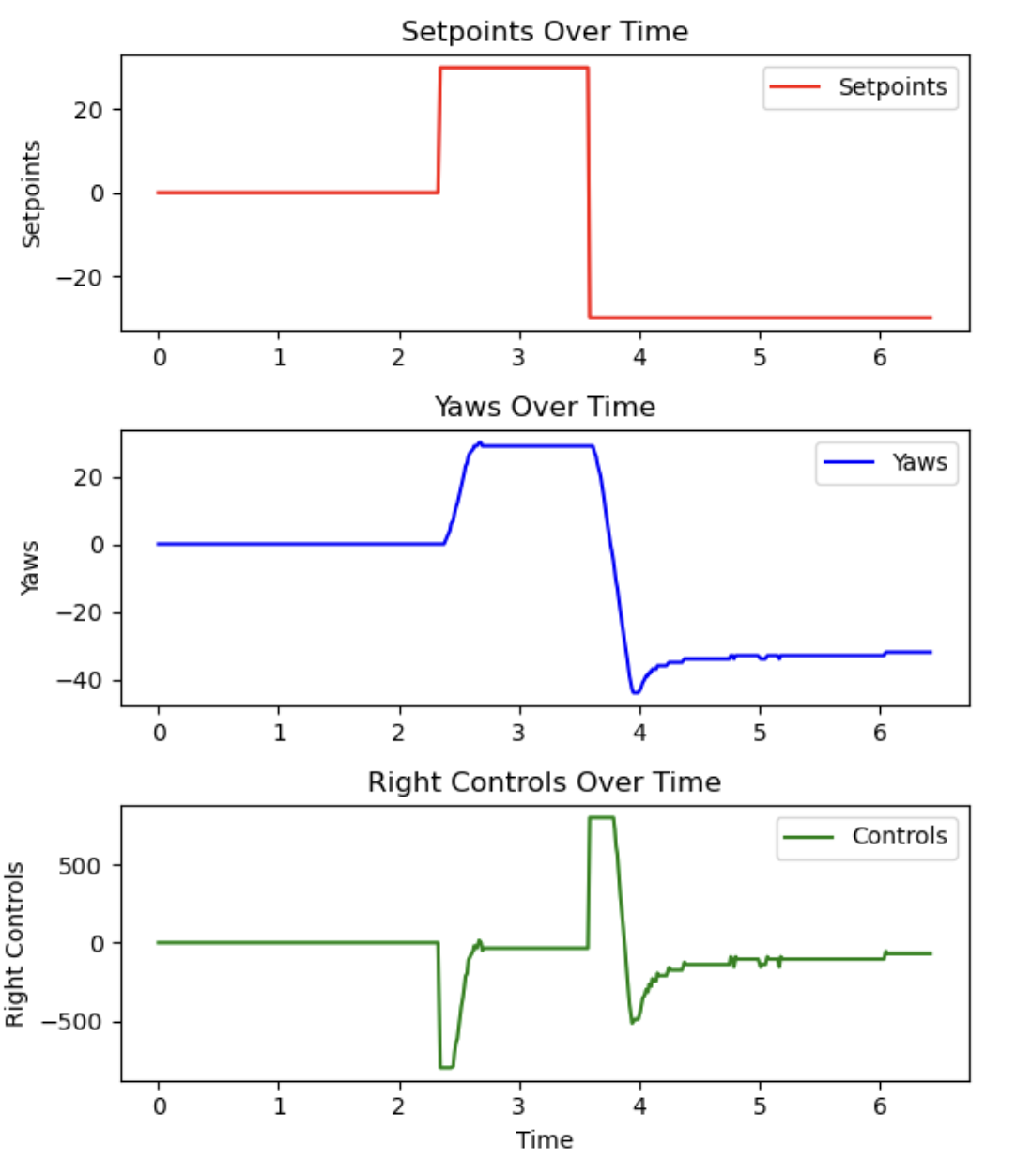
Finally, I use matplotlib to visualize the data, which can give us a better view of the system.
2. Consider adding code snippets as necessary to showcase how you implemented this on Arduino and Python
Arduino
In the loop() function,
if (auto_running) {
    if (!prev_auto_running) {
      ...
    }
    else {
        // calculate elapsed time only when auto running
        elapsed_ms = curr_ms - start_ms;

        distance = readDistance(0);
        gyr_z = readGyrZ();
        yaw -= gyr_z * (curr_ms - prev_ms) / 1000.0;

        // keepDistanceToWall(goal_distance, distance);
        keepYaw(goal_yaw, (int16_t)yaw);

        // save current record to array
        saveCurrRecordToArray();
    }
}
I read the distance and gyroscope data in every loop when the robot is in auto_running state and save current record to an array.
void saveCurrRecordToArray() {
    ControllerRecord ctrl_record = getCtrlRecord();
    if (record_ptr < MAX_RECORDS_LEN) {
        records[record_ptr].timestamp_ms = elapsed_ms;
        records[record_ptr].yaw = yaw;
        records[record_ptr].setpoint_yaw = goal_yaw;
      	...
        record_ptr++;
    }
}
In the handleCommand() function, I add the code to deal with SEND_HISTORY_DATA command.
case GET_HISTORY_DATA: {
    // forbidden transfering history data when robot is auto running
    if (auto_running) {
        tx_estring_value.append("Failed: auto running, try later");
        tx_characteristic_string.writeValue(tx_estring_value.c_str());
        break;
    }

    const Record *records;
    uint16_t records_size = getHistoryRecords(&records);
    tx_estring_value.clear();
  	...

    for (int i = 0; i < records_size; i++) {
      	// send all history records
        putARecordToTxEstring(records + i, i);
        tx_characteristic_string.writeValue(tx_estring_value.c_str());
    }
    break;
}
Python
parse_str2data is used to parse the string data into parts that contain the original data.
def parse_str2data(ss):
    idx, data = ss.split(':')
    timestamp, distance, setpoint_distance, yaw, setpoint_yaw, \
    	left_ctrl, right_ctrl, left_pwm, right_pwm = data.split('|')
    ...
    timestamps_ms.append(int(timestamp))
    distances.append(int(distance))
    setpoint_yaws.append(int(setpoint_yaw))
		...
    right_pwms.append(int(right_pwm))
The above function is registered as a callback function to handle RX_STRING
def notification_handler(uuid, byte_array):
    data_str = ble.bytearray_to_string(byte_array)
    parse_str2data(data_str)
ble.start_notify(ble.uuid['RX_STRING'], notification_handler)
Finally the graph is drawed
def plot_graph():
    timestamps_s = [t / 1000.0 for t in timestamps_ms]
    fig, (ax1, ax2, ax3) = plt.subplots(3, 1, figsize=(6, 7))

    ax1.plot(timestamps_s, setpoint_yaws, label='Setpoints', color='red')
    ax1.set_title('Setpoints Over Time')
    ax1.set_ylabel('Setpoints')
    ax1.legend()

    ax2.plot(timestamps_s, yaws, label='Yaws', color='blue')
    ax2.set_title('Yaws Over Time')
    ax2.set_ylabel('Yaws')
    ax2.legend()

    ax3.plot(timestamps_s, right_controls, label='Controls', color='green')
    ax3.set_title('Right Controls Over Time')
    ax3.set_ylabel('Right Controls')
    ax3.set_xlabel('Time')
    ax3.legend()

    plt.tight_layout()
    plt.show()
Lab Tasks
1. P/I/D discussion (Kp/Ki/Kd values chosen, why you chose a combination of controllers, etc.)
I use PID controller, the parameters are set as follows:
PIDParam angle_param = {
    .Kp = 35,
    .Ki = 1,
    .Kd = 15
};

std::pair<int16_t, int16_t> angle_pid(int16_t error) {
    int16_t control = angle_param.Kp * error
        + angle_param.Kd * (error - angle_var.prev_error)
      	+ angle_param.Ki * angle_var.integral;
    // constrain the control value within limitation
    if (control >= MAX_CONTROL) control = MAX_CONTROL;
    if (control <= MIN_CONTROL) control = MIN_CONTROL;
    angle_var.prev_error = error;
  	angle_var.integral += error;
    return std::make_pair(-control, control);
}
Kp ensures that the robot always return to the original direction when pushed away
Kd prevents overshoot
Ki eliminate the cumulative error
P controller is the most basic controller, but using proportional control itself will lead to high oscillation. So I add the D controller to prevent overshoot. Now that PD controller can handle most situations, but the variable that we try to control may vary a little from the expected value, the I controller solves that. It adds error of all time iterations together in order to magnify the influence of cumulative error to the controller.
So I choose a combination of all three of them to be a PID controller.
2. Range/Sampling time discussion
Range
The default range for the Sparkfun 9DoF IMU is +-250 degrees per second, which is enough for this lab, as the maximum rotation speed is no more than 150 dps.
The smaller sensor range has better accuracy, so I use the default dps250 scale.
Sampling Time
The robot returns an array of history data that has size 842 over 12 seconds:
ble.send_command(CMD.GET_HISTORY_DATA, "")
"""
Size of records array: 842
"""
so the approximate sampling rate is 842/12s = 70Hz.
3. Graphs, code, videos, images, discussion of reaching task goal (Graph data should at least include theta vs time)
Graphs

Videos
and this,
4. (5000) Wind-up implementation and discussion
There is a limit set for angle_var.integral so that it will not go extremely high and increase the oscillation.
Add the upper and lower bound of integrator and prevent the problem:
const int INTEG_BOUND = 200;

int16_t control = pos_param.Kp * error + pos_param.Kd * (error - prev_error) + Ki * angle_var.integral;

angle_var.integral += error;
if (angle_var.intergral > INTEG_BOUND) {
  	angle_var.integral = INTEG_BOUND;
}
else if (angle_var.integral < -INTEG_BOUND) {
		angle_var.integral = -INTEG_BOUND;
}

if (control >= MAX_CONTROL) control = MAX_CONTROL;
if (control <= MIN_CONTROL) control = MIN_CONTROL;
prev_error = error;
The wind-up protection is important, because if the robot was prevented from getting close to the goal yaw angle by some outside force, the integral term will continue accumulating. It will get extremely large or even overflow after a period of time, which will cause problems.
With this protection, the intergal term can be kept within a reasonable range, and can be lowered quickly to correct accumulated errors when the robot rotates without resistance.