Lab5
Prelab
1. Clearly describe how you handle sending and receiving data over Bluetooth
In my code, I record the state of the robot in every loop, including timestamp in millisecond, yaw angle, setpoint of yaw angle and the controller value of both side drivers.
During the auto running process where the robot tries to maintain the given status, the transmission over bluetooth is forbiddened to ensure the high frequency of controll loop.
When the controlling process is over, user can send the command “GET_HISTORY_DATA” over bluetooth which will notify the robot to send all of its history records to the laptop over bluetooth. The jupyter server running on the laptop will use a callback function to deal with the history records, then parse and store them.
Finally, I use matplotlib to visualize the data, which can give us a better view of the system.
2. Consider adding code snippets as necessary to showcase how you implemented this on Arduino and Python
Arduino
In the loop() function,
if (auto_running) {
    if (!prev_auto_running) {
      ......
    }
    else {
        // calculate elapsed time only when auto running
        elapsed_ms = curr_ms - start_ms;
        distance = readDistance(0);
        // save current record to array
        saveCurrRecordToArray();
        keepDistanceToWall(goal_distance, distance);
    }
}
I read the distance and gyroscope data in every loop when the robot is in auto_running state and save current record to an array.
void saveCurrRecordToArray() {
    ControllerRecord ctrl_record = getCtrlRecord();
    if (record_ptr < MAX_RECORDS_LEN) {
        records[record_ptr].timestamp_ms = elapsed_ms;
      	records[record_ptr].distance = distance;
      	records[record_ptr].left_pwm = ctrl_record.left_pwm;
        records[record_ptr].right_pwm = ctrl_record.right_pwm;
      	......
        record_ptr++;
    }
}
In the handleCommand() function, I add the code to deal with SEND_HISTORY_DATA command.
case GET_HISTORY_DATA: {
		......
    const Record *records;
    uint16_t records_size = getHistoryRecords(&records);
    tx_estring_value.clear();
  	......

    for (int i = 0; i < records_size; i++) {
      	// send all history records
        putARecordToTxEstring(records + i, i);
        tx_characteristic_string.writeValue(tx_estring_value.c_str());
    }
    break;
}
Python
parse_str2data is used to parse the string data into parts that contain the original data.
def parse_str2data(ss):
    idx, data = ss.split(':')
    timestamp, distance, setpoint_distance, \
    	left_ctrl, right_ctrl, left_pwm, right_pwm = data.split('|')
    ......
    timestamps_ms.append(int(timestamp))
    distances.append(int(distance))
		......
    left_pwms.append(int(left_pwm))
    right_pwms.append(int(right_pwm))
The above function is registered as a callback function to handle RX_STRING
def notification_handler(uuid, byte_array):
    data_str = ble.bytearray_to_string(byte_array)
    parse_str2data(data_str)
ble.start_notify(ble.uuid['RX_STRING'], notification_handler)
Finally the graph is drawed with pwm values shown
def plot_graph():
    timestamps_s = [t / 1000.0 for t in timestamps_ms]

    fig, ax1 = plt.subplots()

    color = 'tab:red'
    ax1.set_xlabel('Time (s)')
    ax1.set_ylabel('Distance')
    ax1.plot(timestamps_s, distances, color=color)
    ax1.tick_params(axis='y')

    ax1.set_ylim(bottom=0)
    ax2 = ax1.twinx()

    color = 'tab:blue'
    ax2.set_ylabel('PWM', color=color)
    ax2.plot(timestamps_s, right_pwms, color=color)
    ax2.tick_params(axis='y', labelcolor=color)

    plt.title('Distance and PWM vs. Time')
    plt.show()
Lab Tasks
1. P/I/D discussion (Kp/Ki/Kd values chosen, why you chose a combination of controllers, etc.)
float Kp = 1.5;
float Ki = 0.0;
float Kd = 20;
-
Kpensures that the robot have the ability to keep the given distance. The largerKpis, the robot moves faster towards the given position. After testing,Kp = 1.5works best for my robot. -
Kdprevents overshoot. It punish the behavior of moving too fast. IfKdis too small or set to 0, the robot will oscillate around the given distance. At first I triedKd = 5, 10, 15, but the robot will still collide to the wall when the initial speed is high. FinallyKd = 20works best. -
Kieliminate the cumulative error. I find that the cumulative error in this Lab is small enough to ignore, so I setKito zero.
So eventually, the controller type that I use is PD controller.
2. Range/Sampling time discussion
I choose Medium range for distance sensor because it provides a relatively large detection range and low delay.
The distance sensor behaves normally (has low standard deviation) in this Lab settings.

The sampling time is about 12ms. So the frequency of the main loop() function is about 1000ms/12ms = 83Hz. It is faster than the ToF sensor because I set blocking=false when reading the distance sensor data. My program just use distance data before if the new data is not ready to read.
3. Graphs, code, videos, images, discussion of reaching task goal (Graph data should include Tof vs time and Motor input vs time)
Codes
This is the core function that is called every loop in main.ino.
keepDistanceToWall(goal_distance, distance);
The function is provided by the following code in controller.cpp:
int16_t pid(int16_t error) {
    int16_t control = Kp * error + Kd * (error - prev_error);
    if (control >= MAX_CONTROL) control = MAX_CONTROL;
    if (control <= MIN_CONTROL) control = MIN_CONTROL;
    prev_error = error;
    return control;
}

void keepDistanceToWall(uint16_t setpoint, uint16_t distance) {
    int16_t control = pid(distance - setpoint);
    straight_control(control);
}
straight_controll() is defined here:
void straight_control(int16_t control) {
    // map control signal to actual pwm in order to
    // eliminate the influence of dead band
    ctrl_record.control = control;
    left_wheel_control(control);
    right_wheel_control(control);
}

void left_wheel_control(int16_t control) {
    ctrl_record.left_control = control;
    int16_t left_pwm = 0;
    if (control >= 0) {
        left_pwm = ctrl_pwm_map(control, 0, 1000, 55, 255);
    }
    else {
        left_pwm = ctrl_pwm_map(control, -1000, 0, -255, -30);
    }
    left_wheel_move(left_pwm);
}

void right_wheel_control(int16_t control) {
    ctrl_record.right_control = control;
    int16_t right_pwm = 0;
    if (control >= 0) {
        right_pwm = ctrl_pwm_map(control, 0, 1000, 28, 255);
    }
    else {
        right_pwm = ctrl_pwm_map(control, -1000, 0, -255, -28);
    }
    right_wheel_move(right_pwm);
}
left_wheel_control() and right_wheel_control() have different mapping functions in order to eliminate the influence of the asymmetry of left and right motor output power.
Graphs and Videos
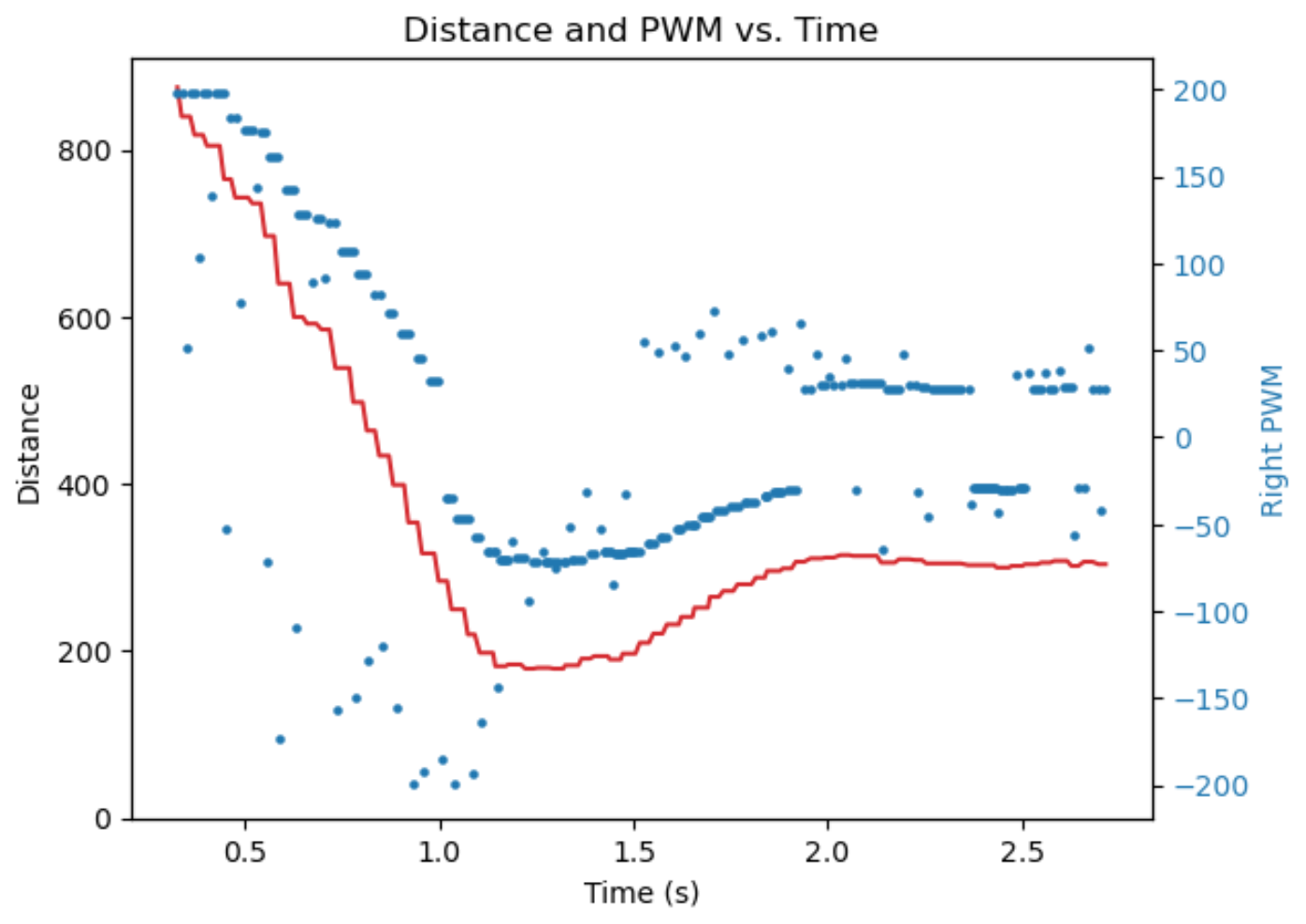
Release from a certain distance and let it run towards the wall

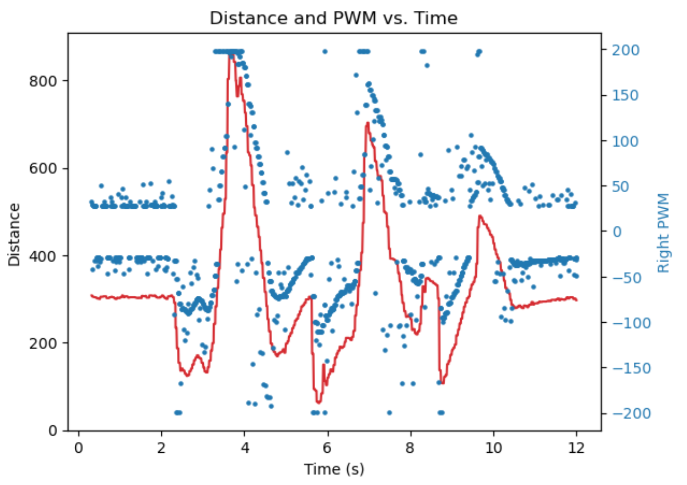
Use feet to interact with it to see its dynamic performance

5. (5000) Wind-up implementation and discussion
Add the upper and lower bound of integrator and prevent the problem:
int16_t control = pos_param.Kp * error + pos_param.Kd * (error - prev_error) + Ki * integral;

integral += error;
if (intergral > 300) integral = 300;
else if (integral < -300) integral = -300;

if (control >= MAX_CONTROL) control = MAX_CONTROL;
if (control <= MIN_CONTROL) control = MIN_CONTROL;
prev_error = error;
The wind-up protection is important, because if the robot was prevented from getting close to the goal distance by some outside force, so integral term will continue accumulating until getting extremely large or overflow, which will cause problems when it is set free.
With this protection, the intergal term can be kept within a reasonable range, and can be lowered quickly to correct accumulated errors when the robot moves without resistance.
6. Simple linear extrapolation algorithm
uint16_t real_distances[2];
uint32_t real_timestamps[2];

uint8_t real_ptr = 0;

void loop() {
		......

    if (isReady(0)) {
        distance = readDistance(0);
        real_distances[real_ptr % 2] = distance;
        real_timestamps[real_ptr % 2] = elapsed_ms;
        real_ptr++;
    }
    else {
        if (real_ptr <= 2) {
            distance = real_distances[real_ptr - 1];
        }
        else {
            int t_now = elapsed_ms;
            int t_prev1 = real_timestamps[(real_ptr - 1) % 2];
            int t_prev2 = real_timestamps[real_ptr % 2];

            int d_prev1 = real_distances[(real_ptr - 1) % 2];
            int d_prev2 = real_distances[real_ptr % 2];

            float k = (float)(t_now - t_prev1) / (float)(t_prev1 - t_prev2);
            distance = k * (d_prev1 - d_prev2) + d_prev1;
        }
    }

   	......
}
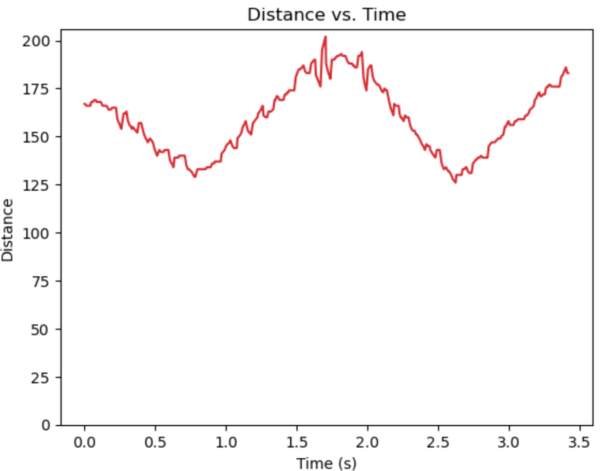
The distance data after linear extrapolation looks like this. It increases the oscillation of the distance data, but provide a better estimation compared to just use the last sensor reading.
