Lab3
Prelab
1. Note the I2C sensor address
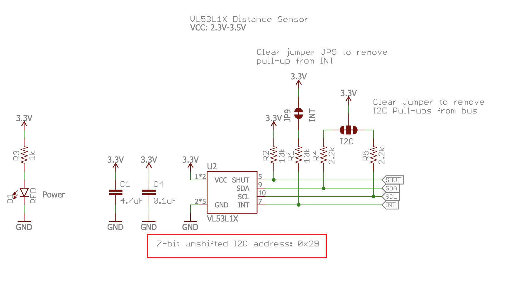
From the datasheet of VL53L1X Distance Sensor, we can read that the I2C sensor address if 0x29.
2. Briefly discuss the approach to using 2 ToF sensors
Although the lab guide suggests using SparkFun VL53L1X 4m Laser Distance Sensor library, it doesnot have a clear and direct example that shows how to use more than 1 ToF sensors simaltaneously. So I choose to use the VL53L1X developed by Pololu.
Load the ContinuousMultipleSensors.ino file from its Examples. It provide the sketch of using mulitple ToF sensors. I do the following job to make it compatible with my own robot.
(1) Solder two seperate wires to their shutdown pins
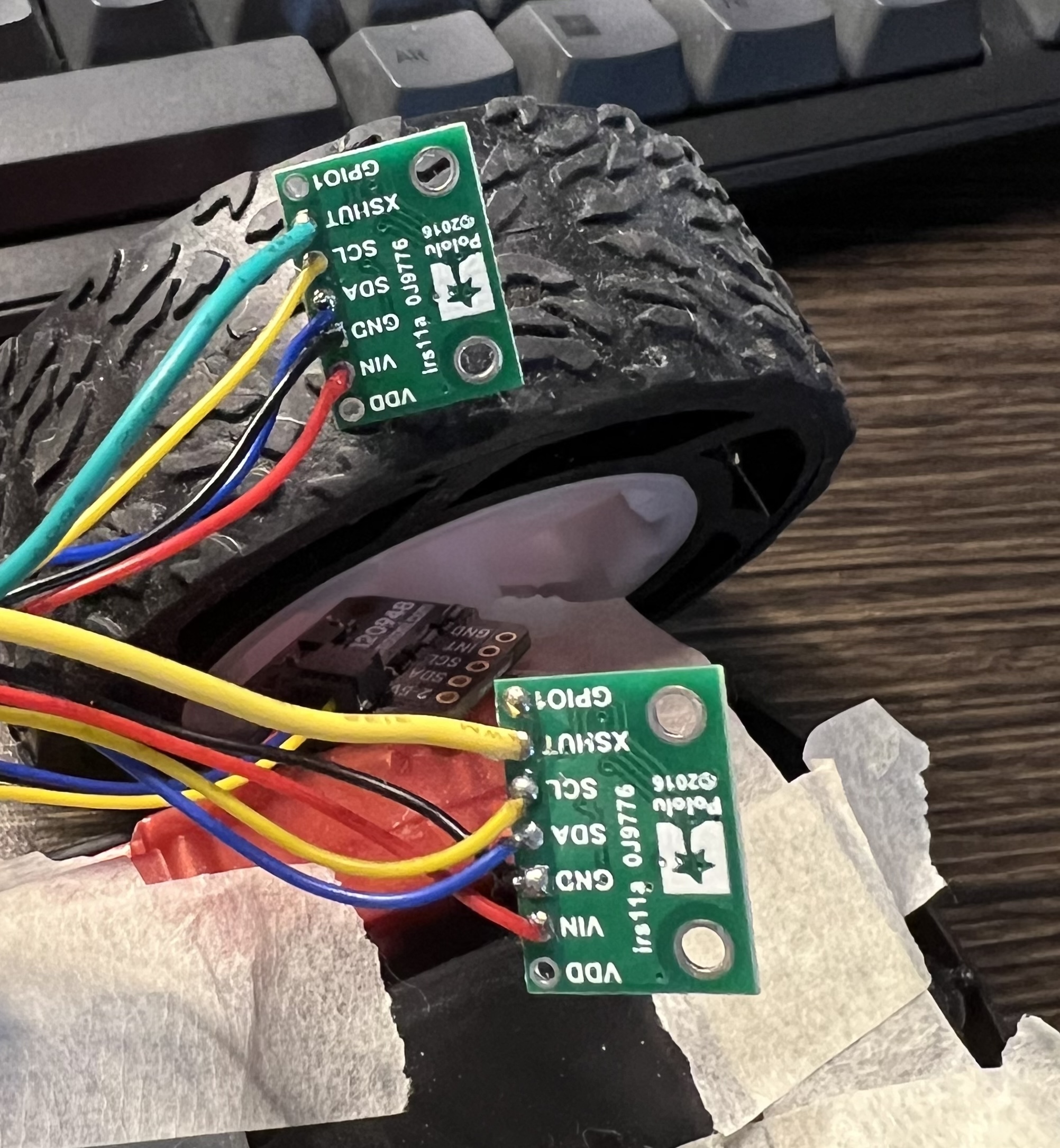
- Green wire connects pin 15 and the XSHUT of front ToF sensor
- Yellow wire connects pin 16 and the XSHUT of side ToF sensor
(2) Configure shutdown pins number and reset their address
const uint8_t xshutPins[sensorCount] = { 15, 16 };

for (uint8_t i = 0; i < sensorCount; i++)
{
  // Stop driving this sensor's XSHUT low. This should allow the carrier
  // board to pull it high. (We do NOT want to drive XSHUT high since it is
  // not level shifted.) Then wait a bit for the sensor to start up.
  pinMode(xshutPins[i], INPUT);
  ......

  // reset sensor I2C address
  sensors[i].setAddress(0x2A + i);
  ......
}
3. Briefly discuss placement of sensors on robot and scenarios where you will miss obstacles
One installed on the front of the robot and the other on the right side of the robot.
Scenarios that may miss obstables:
- The obstacles are on the left or on the back of the robot
- The obstacles are too high or too low
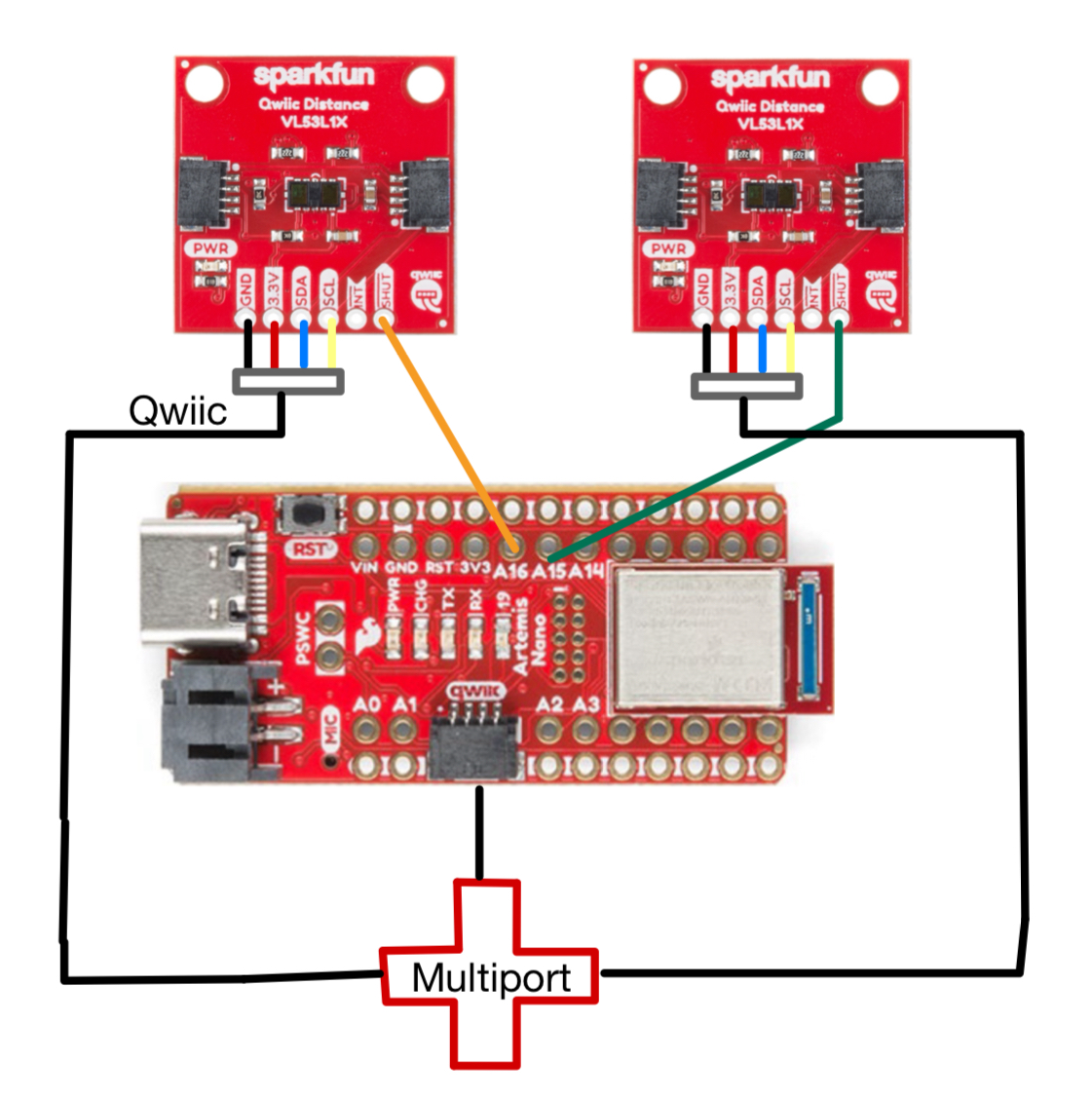
4. Sketch of wiring diagram
Lab Tasks
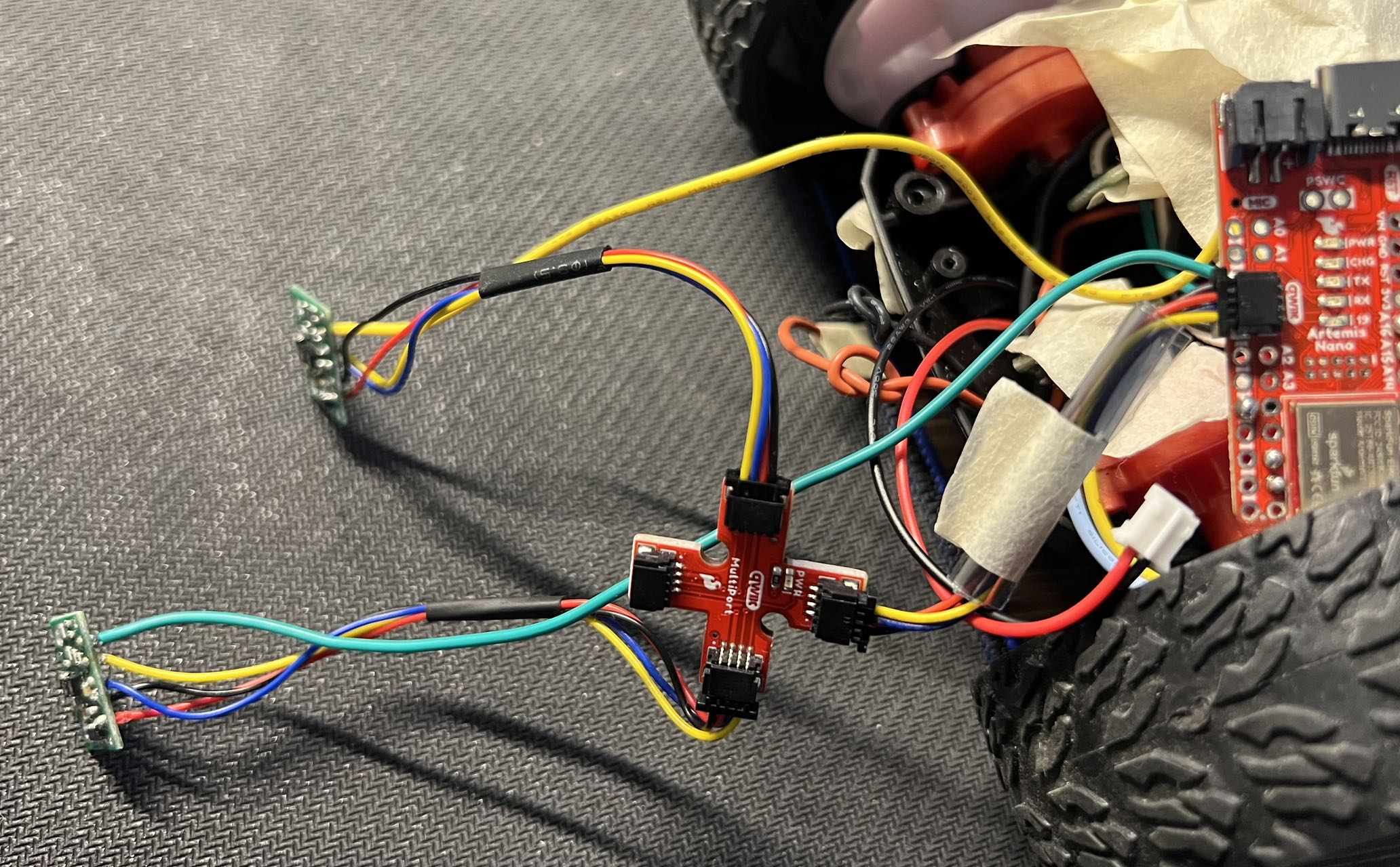
1. Picture of your ToF sensor connected to your QWIIC breakout board
2. Screenshot of Artemis scanning for I2C device (and discussion on I2C address)
I add the following code to display the process of scanning for I2C devices:
for (uint8_t i = 0; i < sensorCount; i++)
{
	......

  uint8_t addr = sensors[i].getAddress();
  Serial.printf("Detected sensor %d with address %d\n", i, addr);
  ......

  // Each sensor must have its address changed to a unique value other than
  // the default of 0x29 (except for the last one, which could be left at
  // the default). To make it simple, we'll just count up from 0x2A.
  sensors[i].setAddress(0x2A + i);

  Serial.printf("Set new address %d\n", 0x2A + i);
}
The screenshot:
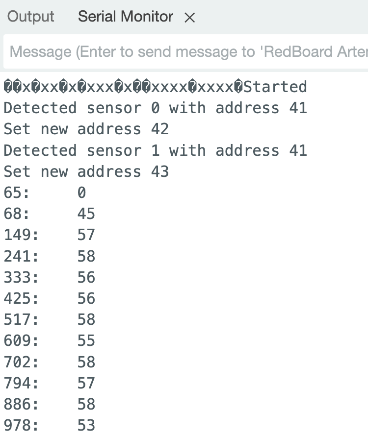
41 in decimal is 0x29 in hexadecimal, which is same as the initial i2c address.
The newly set address is 42 and 43, which correspond to 0x2A and 0x2B.
Now the 2 ToF sensors have two different I2C address, so they can all be read on the same time.
3. Discussion and pictures of sensor data with chosen mode
From 100mm to 1000mm, I sampled 20 data points at each position with three diffrent modes, and plot them on the graph.

The short mode has least standard deviation. The deviation of sample datapoints at each position of short mode is plotted below:
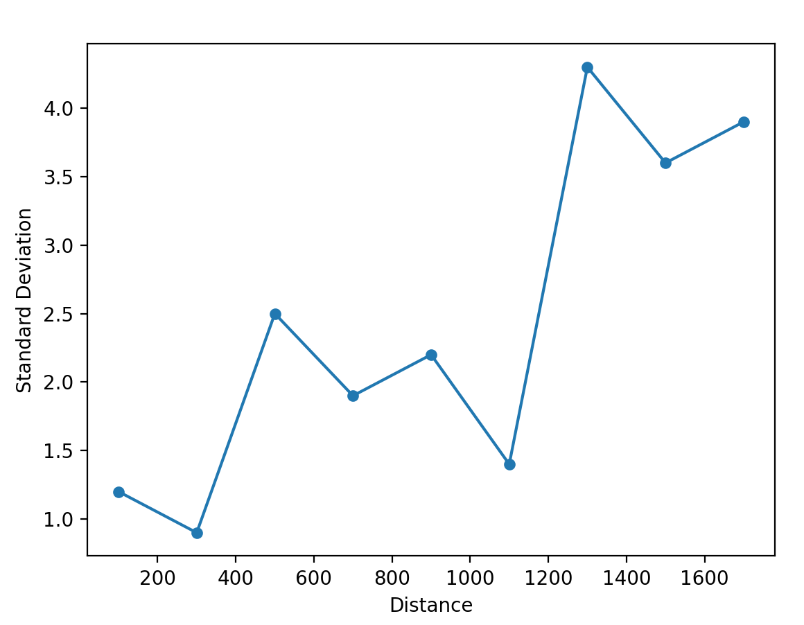
It can be seen from the plot that when the distance is larger than 1.3m, the standard deviation of the data points has a large leap. So if we choose Short Mode, we’d better keep the obstacles within 1.3m of the ToF sensor.
4. 2 ToF sensors: Discussion and screenshot of sensors working in parallel
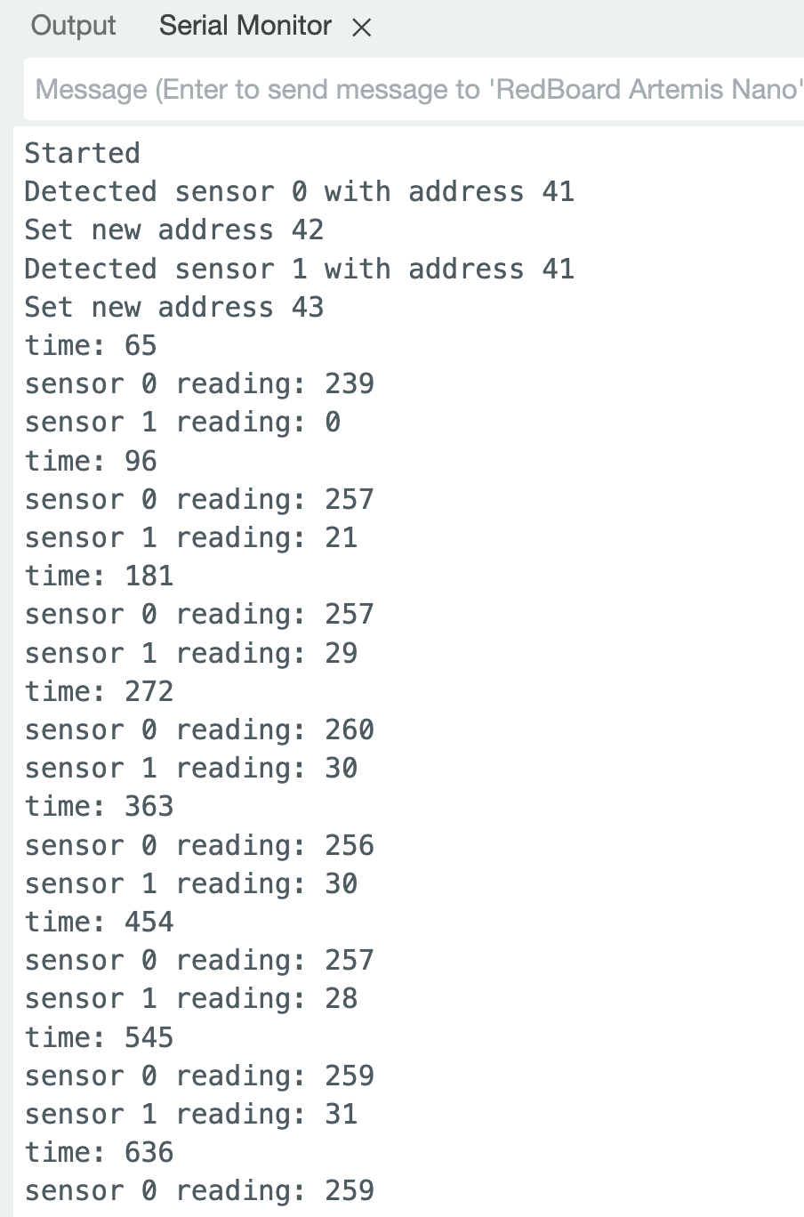
Two ToF sensors are connected through Qwiic connect system to the Artemis board, with the help of a multiport board. However, the default address of I2C address are the same for two ToF sensors, so we need to modify the hardware to support two sensors working in parellel.
The first thing I do is solder two seperate wires to each of the sensor’s XSHUT pin. And they are all pulled LOW in order to disable the sensors. Then one by one, stop driving the XSHUT pin LOW, which will enable a certain sensor. After that, setting the Distance Mode of current sensor and assign a new address to it, so that later we can directly call the sensors without manipulating the XSHUT pins.
Now all the sensors can work in the same time. Below is the screenshot:
5. Tof sensor speed: Discussion on speed and limiting factor; include code snippet of how you do this
I record the distance data to an array without blocking the main loop of the program,
Record records[MAX_RECORDS_LEN];

uint16_t record_ptr = 1;

void saveCurrRecordToArray() {
    ControllerRecord ctrl_record = getCtrlRecord();
    if (record_ptr < MAX_RECORDS_LEN) {
        records[record_ptr].timestamp_ms = elapsed_ms;
        records[record_ptr].distance = distance;
        record_ptr++;
    }
}

void loop() {
		......
    // While central is connected
    while (central.connected()) {
          ......
          curr_ms = millis();
          elapsed_ms = curr_ms - start_ms;

          distance = readDistance();
          saveCurrRecordToArray();
          ......
    }
}
And send the recored data to laptop over bluetooth:
void handleCommand() {
  	......
  	switch (cmd_type) {
        ......
        case GET_HISTORY_DATA: {

            const Record *records;
            uint16_t records_size = getHistoryRecords(&records);

            tx_estring_value.clear();
            tx_estring_value.append("Size of records array: ");
            tx_estring_value.append(records_size);
            tx_characteristic_string.writeValue(tx_estring_value.c_str());

            for (int i = 0; i < records_size; i++) {
                putARecordToTxEstring(records + i, i);
                tx_characteristic_string.writeValue(tx_estring_value.c_str());
            }
            break;
        }
        ......
		}
}
When the Distance Mode changes or the parameter inside sensors[i].startContinuous(period_ms); changes, the average of sensor reading intervals are subject to change. I tested several groups of data and list them in the tables below.
| Distance Mode: Long | startContinuous(50) | startContinuous(100) | startContinuous(200) |
|---|---|---|---|
| Average Interval (ms): | 92 | 92 | 186 |
| Distance Mode: Medium | startContinuous(33) | startContinuous(100) | startContinuous(200) |
|---|---|---|---|
| Average Interval (ms): | 61 | 92 | 185 |
| Distance Mode: Short | startContinuous(20) | startContinuous(100) | startContinuous(200) |
|---|---|---|---|
| Average Interval (ms): | 37 | 92 | 185 |
We can conclude that there are 3 factors that limit ToF sensor speed:
- Frequency of the main loop: If their are too many code in the main loop, or some code block the running of the main loop function, the reading of ToF sensors will be delayed.
- Parameter in the sensor.startContinuous(): The smaller the parameter is, the faster the sensor reads, but there is a lower bound affected by distance mode.
- Tof sensor speed: When set to Short, sensor has the highest possible reading speed, when set to Long, sensor has the lowest possible reading speed.
The minimal sensor reading interval is 37ms, which is 27Hz.
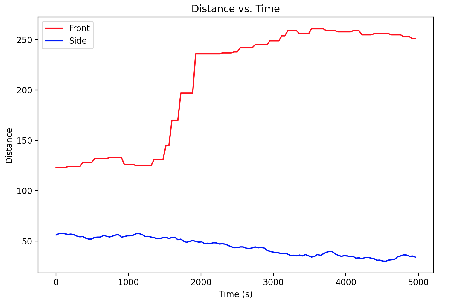
6. Time v Distance: Include graph of data sent over bluetooth (2 sensors)
7. (5000) Discussion on infrared transmission based sensors
Infrared (IR) distance sensors are a popular choice for many applications due to their non-contact nature, which makes them ideal for measuring distances without physically touching the object.
There are different types of IR based sensors:
- Infrared Time-of-Flight (ToF) Sensors
- Pros: High accuracy and precision; Immune to ambient light; Good range
- Cons: High Cost; Sensitive to materials
- Infrared Reflective Sensors
- Pros: Cost-effective; Easy to integrate and use
- Cons: Limited range; Sensitive to ambient light
- Infrared Array Sensors
- Pros: Spatial awareness
- Cons: High complexity and cost
8. (5000) Sensitivity of sensors to colors and textures
Principle Analysis
The design of the infrared depth sensor is based on the principle of Time of Flight (TOF), that is, the sensor emits the modulated near-infrared light, which is reflected after the object, and the sensor calculates the distance from the object by calculating the time difference or phase difference between the emission and reflection of the light.

Because the light is infrared, not in the spectrum of visable light, the color of the reflection plane will not have a direct impact on the IR sensor.
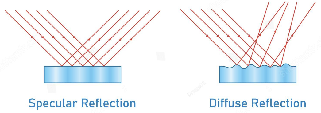
But if the plane is too smooth that it causes speccular reflection instead of diffuse reflection, it is very likely that the receivers will not detect any light from the smooth surface.
Colors
I tried 3 different colors: orange, blue and green. Below is the comparison:
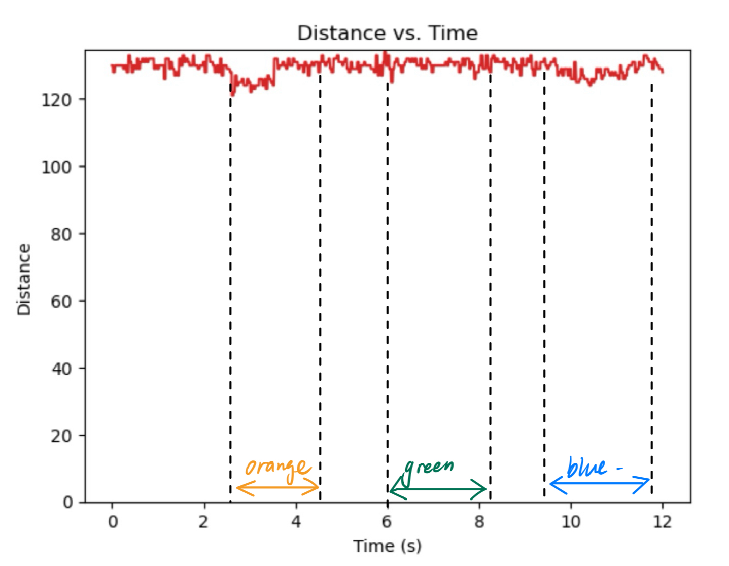
We can see that the colors have little influence on the accuracy of the ToF sensors.
Textures
I tried 3 different textures: white wall, glass (the screen of my iPad) and metal (the back panel of my iPad), and below is the distance sensor reading:
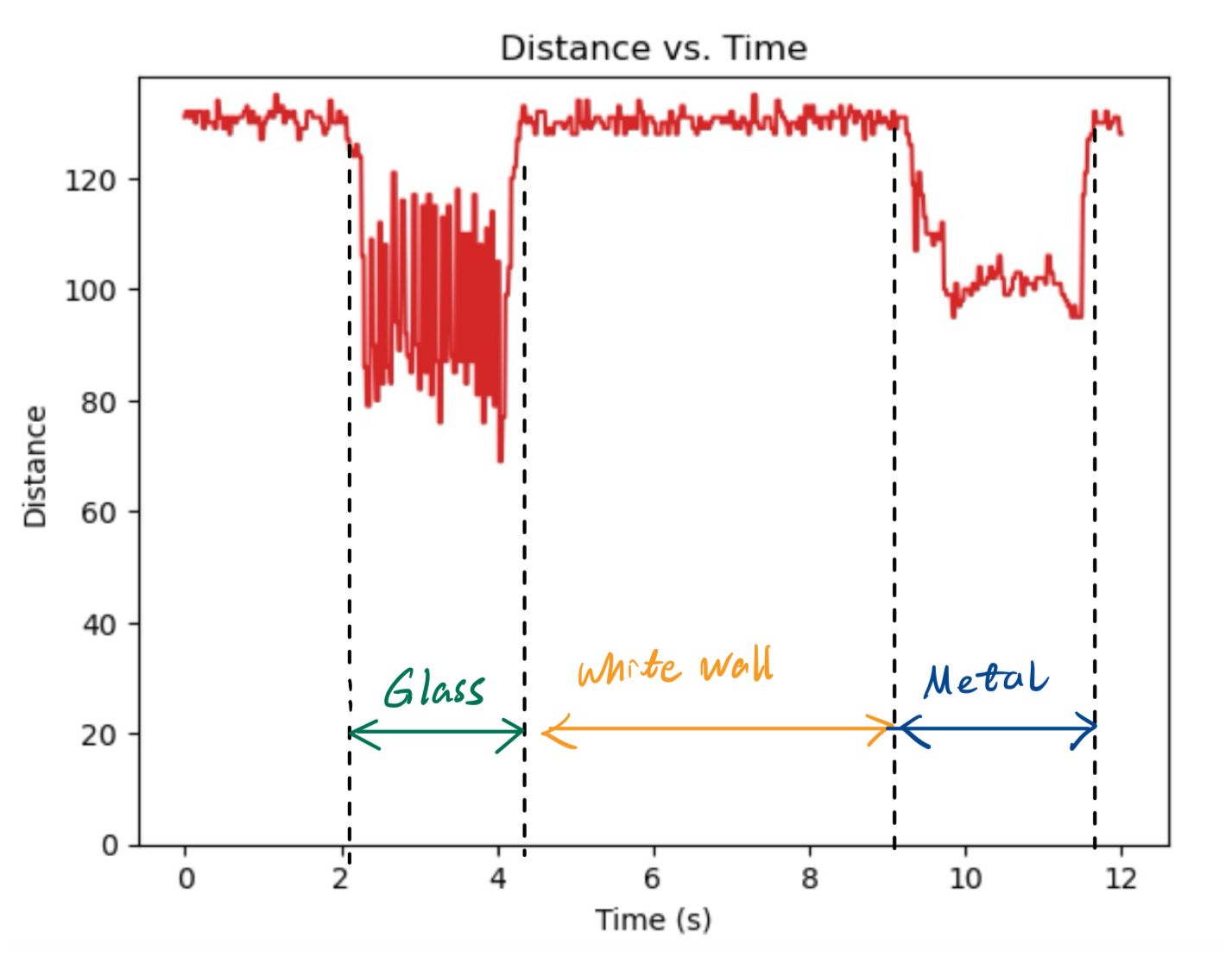
On the conditions of wall and metal, the ToF sensor works normally. Howver, when the reflection plane is glass, the accuracy of the ToF sensors drops sharply, which means the data of ToF sensor have large standard deviation, adding uncertainty to the data.