Lab2
Lab 2
Setup the IMU
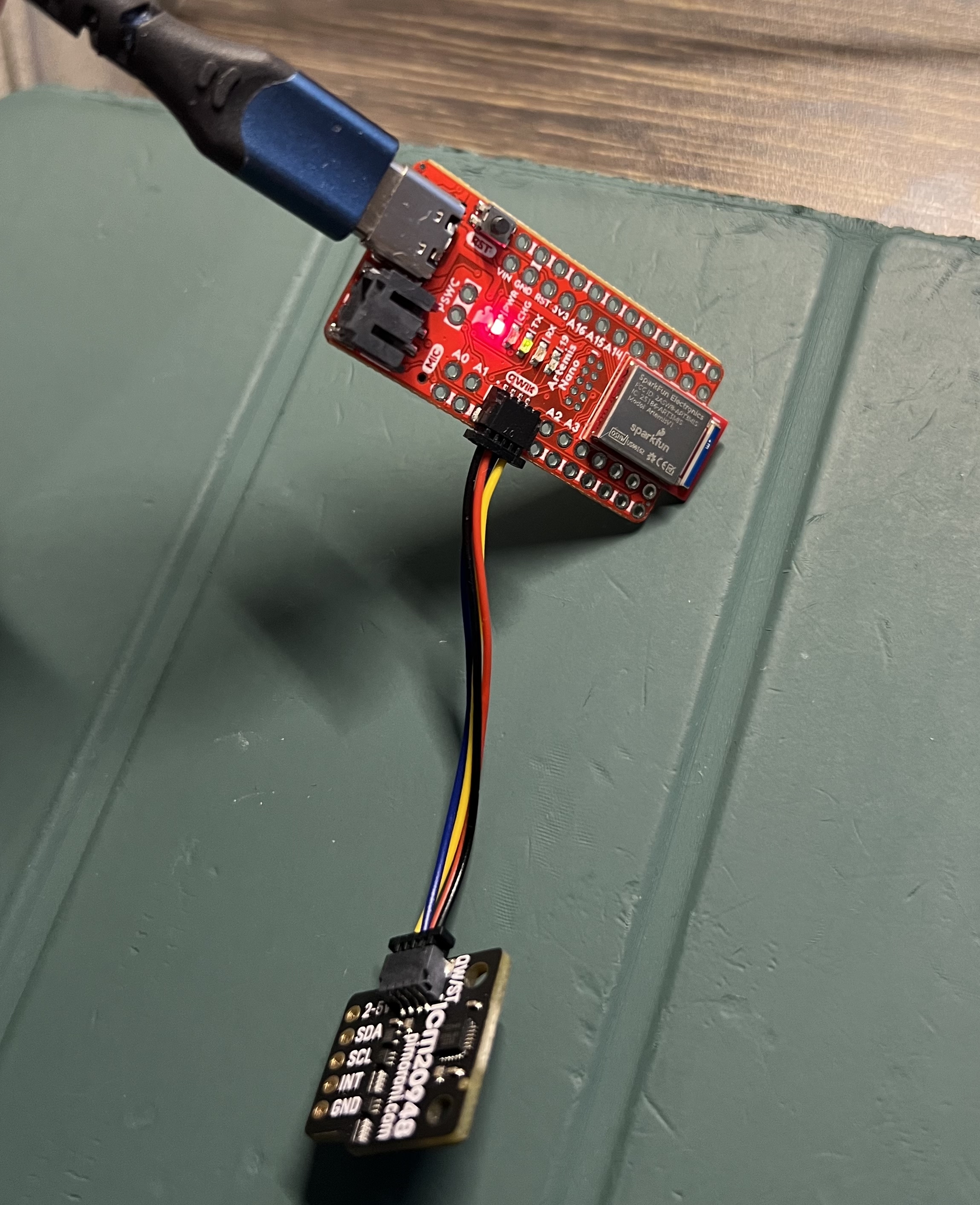
1. Picture of your Artemis IMU connections
2. Show that the IMU example code works
I add the LED blink when Artemis power on.
void setup()
{
  // Blink the LED 3 times slowly on start up
  int cnt = 0;
  while (cnt < 3) {
    digitalWrite(LED_BUILTIN, HIGH);
    delay(800);
    digitalWrite(LED_BUILTIN, LOW);
    delay(800);
    cnt += 1;
  }
  ...
}
3. AD0_VAL definition discussion
According to the description in the IMU_Example.ino : “On the SparkFun 9DoF IMU breakout the default is 1, and when the ADR jumper is closed the value becomes 0”. However, we can’t read the data from IMU when AD0_VAL is set to the default value 1, which throws the message:
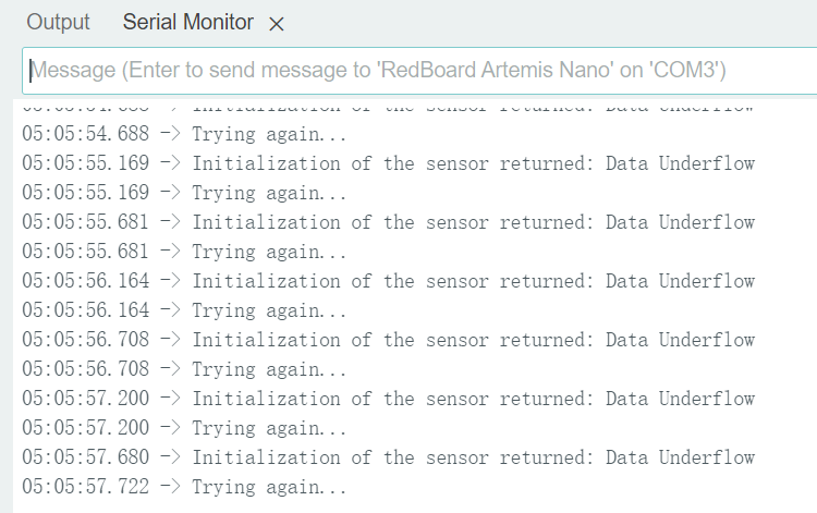
When modified that value to 0, the data from IMU can now be read normally.
4. Acceleration and gyroscope data discussion
The gyroscope data is close to zero when holding still. Gyro data for a given axis increases when rotating around the axis.
Accelerometer
1. Image of output at {-90, 0, 90} degrees for pitch and roll (include equations)
I add two functions:
convert2Attitude converts the raw accelerometer data to pitch and roll angle.
void convert2Attitude(ICM_20948_I2C *sensor, Attitude* att) {
  float pitch_rad = atan2(sensor->accX(), -sensor->accZ());
  float roll_rad = atan2(sensor->accY(), -sensor->accZ());
  att->pitch = pitch_rad * 180.0 / M_PI;
  att->roll = roll_rad * 180.0 / M_PI;
}
printAttitude prints formatted attitude values.
void printAttitude(Attitude *att) {
  SERIAL_PORT.print("Pitch [ ");
  printFormattedFloat(att->pitch, 3, 2);
  SERIAL_PORT.print(" ], Roll [ ");
  printFormattedFloat(att->roll, 3, 2);
  SERIAL_PORT.print(" ]");
  SERIAL_PORT.println();
}
- 0 degree pitch & roll
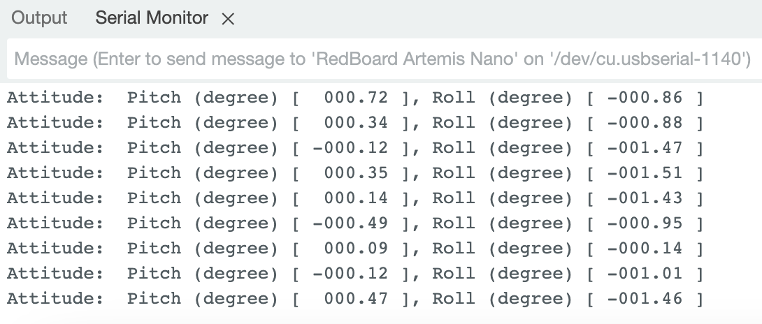
- 90 degrees pitch
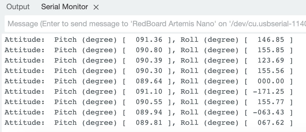
- -90 degrees pitch
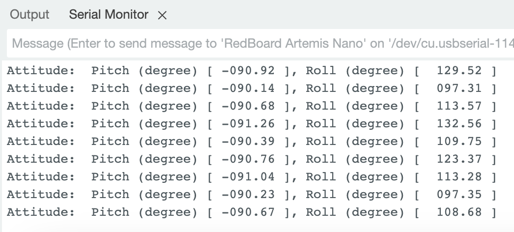
- 90 degrees roll
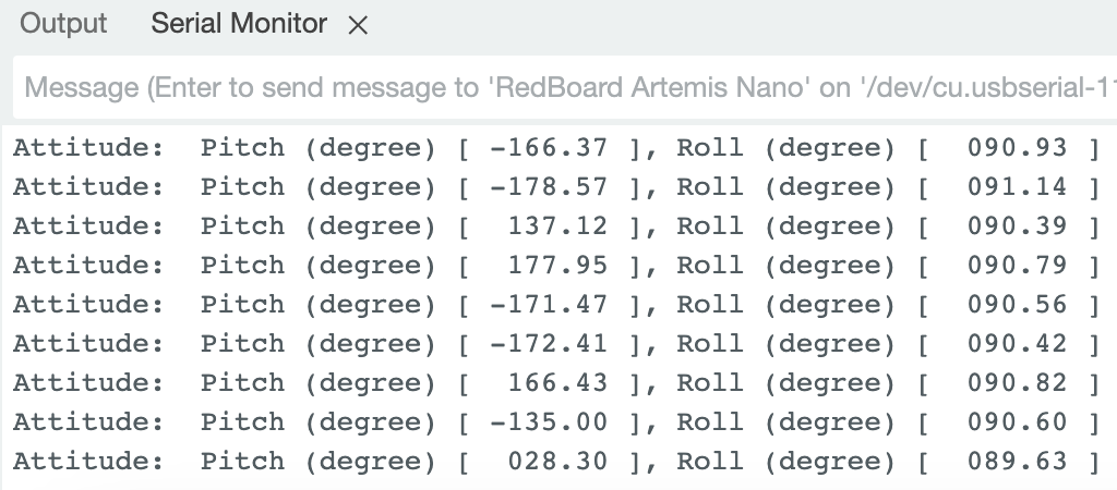
- -90 degrees roll
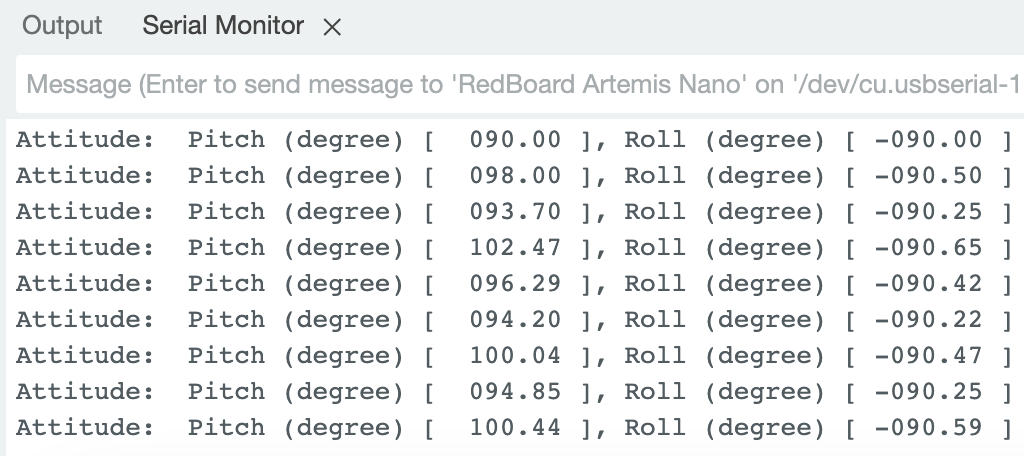
2. Accelerometer accuracy discussion
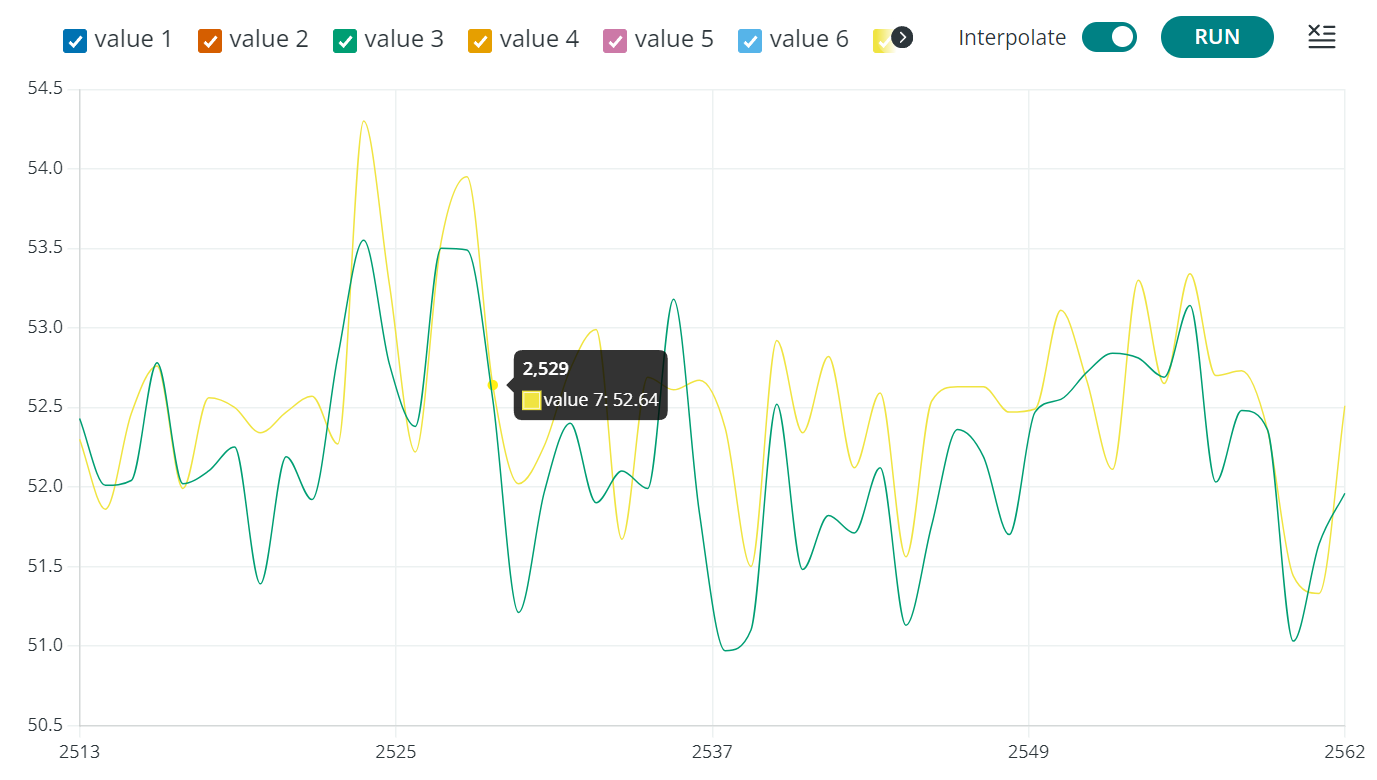
The pitch and roll data calculated by accelerometer data has large noise, it vibrates a lot even when the IMU is hold still.
3. Noise in the frequency spectrum analysis
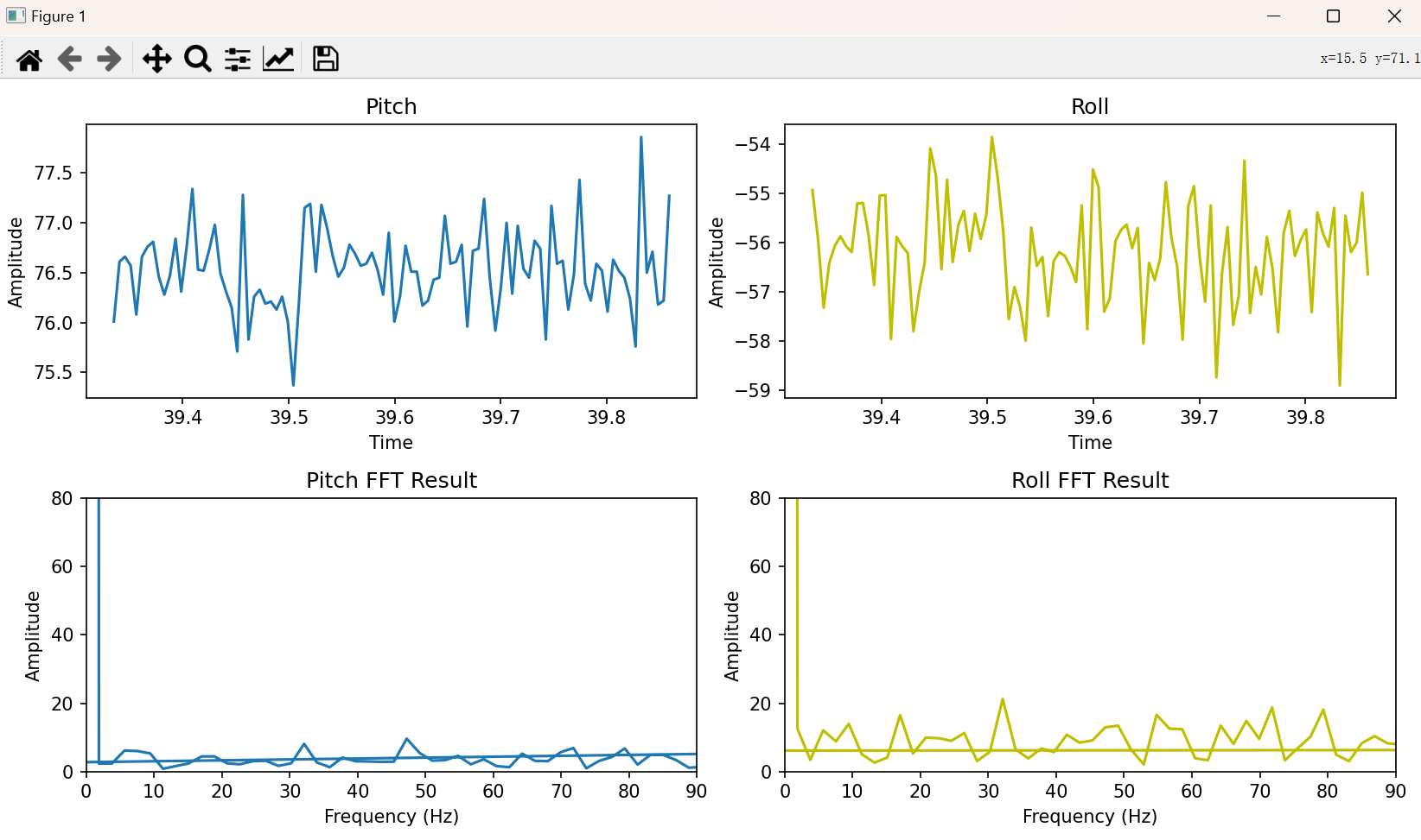
(a) Include graphs for your fourier transform
(b) Discuss the results
There exists a lot of high frequency noise in the accelerometer data. However, we can only operate the car in a relatively low frequency, for example, no more than 10Hz. So a low pass filter is needed.
Gyroscope
1. Include documentation for pitch, roll, and yaw with images of the results of different IMU positions
void loop() {
    if (myICM.dataReady())
    {
        prev_time = curr_time;
        curr_time = millis();

        ...

        float gyr_x = myICM.gyrX();
        att.roll -= gyr_x * (curr_time - prev_time) / 1000.0;
        float gyr_y = myICM.gyrY();
        att.pitch -= gyr_y * (curr_time - prev_time) / 1000.0;
        float gyr_z = myICM.gyrZ();
        att.yaw -= gyr_z * (curr_time - prev_time) / 1000.0;

        printAttitude(&att);

    }
    ...
}
The serial plotter shows the curve of the angular data calculated by gyroscope.
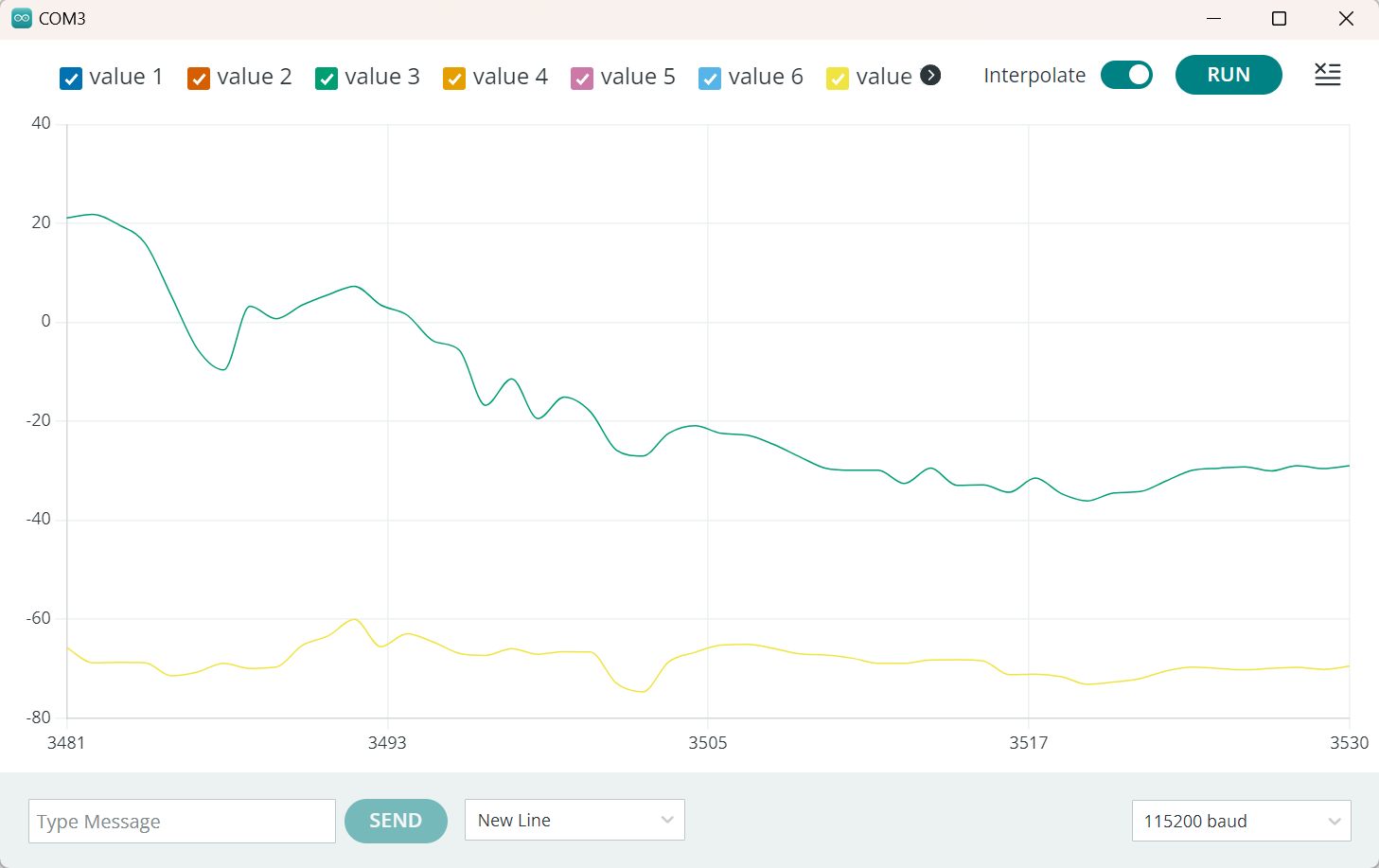
The angular data calculated by gyroscope has less noise but will drift over time.
2. Demonstrate the accuracy and range of the complementary filter, and discuss any design choices
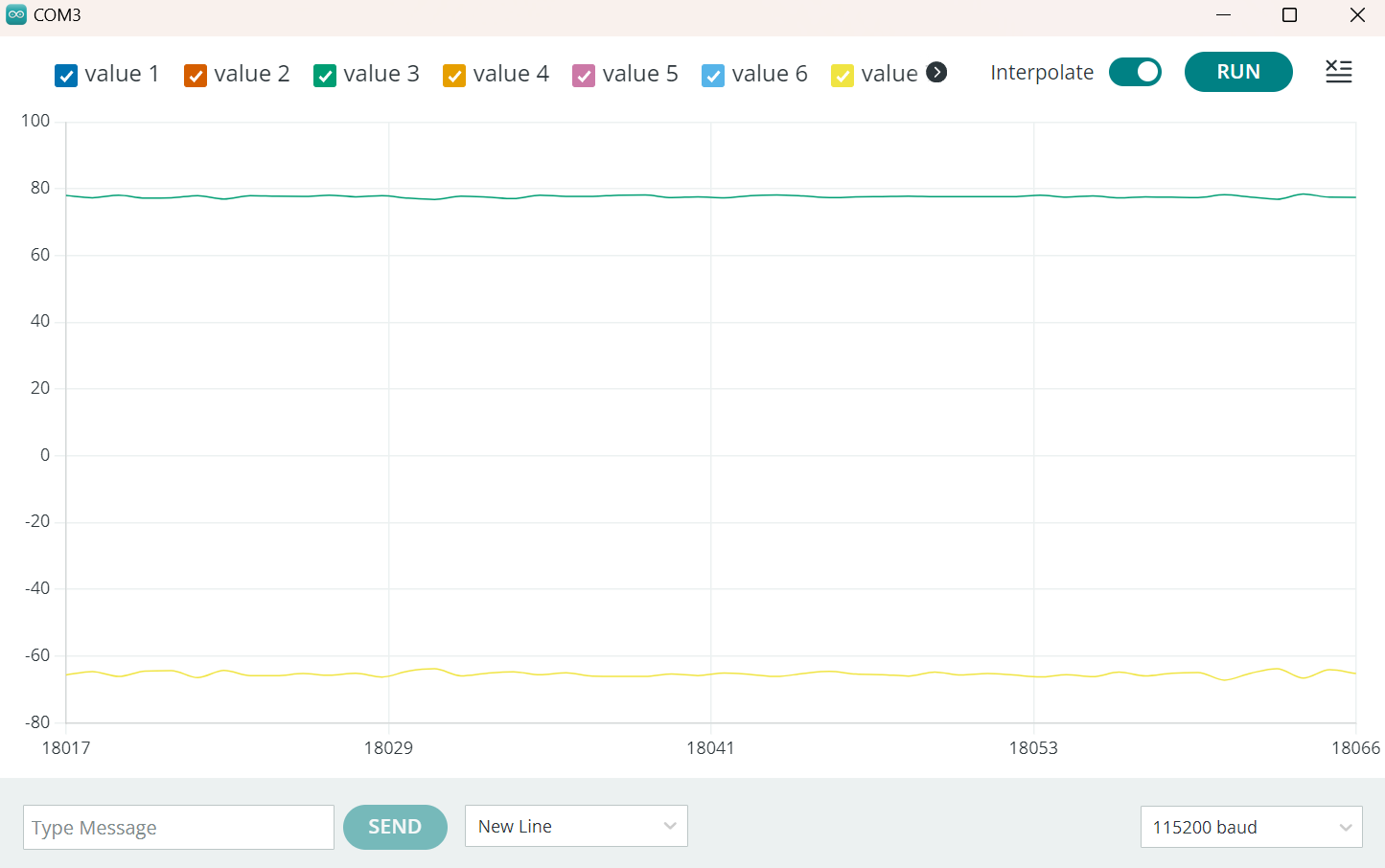
Complementary filter has less noise than pure accelerometer data, and will not drift over time like pure gyroscope data.
att.roll = (1 - alpha) * (att.roll + gyr_x * dt) + alpha * acc_x;
att.pitch = (1 - alpha) * (att.pitch + gyr_y * dt) + alpha * acc_y;
att.yaw = att.yaw + gyr_z;
I choose the parameter alpha in complementary filter to be 0.01;
Sample Data
1. Speed of sampling discussion
By removing all the delay() and Serial.print() statements in the code, the code can run at about 250Hz. By storing time stamp and sensor data in a buffer, the code can run even faster, at a frequency of 330Hz.
This rapid sampling rate can lead to an accumulation of data within a short period of time. The data was organized as string arrays and transmitted to Jupyter through bluetooth.
2. Demonstrate collected and stored time-stamped IMU data in arrays
The data stored in Arduino in this form, with buffer size 2000;
struct Attitude {
  float roll = 0;
  float pitch = 0;
  float yaw = 0;
};

Attitude att;

const int buffer_size = 2000;
int end_pt = 0;
int time_stamps[buffer_size];
Attitude atts[buffer_size];
The data stored in Jupyter has this form:
def parse_to_time_data(ss):
    result = ss.split('|')
    time_ms = result[0]
    roll = result[1]
    pitch = result[2]
    yaw = result[3]
    time_stamps.append(time_ms)
    roll_arr.append(roll)
    pitch_arr.append(pitch)
    yaw_arr.append(yaw)
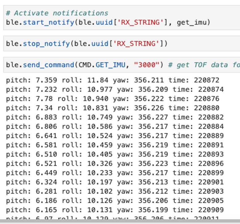
3. Demonstrate 5s of IMU data sent over Bluetooth
Each IMU data frame haws 3 float variable and 1 int variable, which takes 14B space, the sample rate was set to about 300Hz, which takes 4.2KB/s. The Artemis has 384KB of RAM, so there is enough space for 5s of IMU data to be transmitted through Bluetooth.
